This is a do-it-yourself open-source low-cost simple wireless buzzword-free model-railroad steering application for big-scale engines.
For a while I have involved myself into the DCC-EX project which designs an open source low-cost DCC command station. While this is a very good alternative for my N-scale layout, I was doubtful if DCC was the right way to control my 1:32 (Scale I) engines. In contrast to N-scale the engines are fewer and bigger. Rail contact is always an issue, especially outdoors and I was not sure that DCC signal propagation through the rail is really the right thing to do. In addition to that, both boosters and decoders that are suitable for high currents are expensive and are often sold with the extra LGB pricetag. (If you can afford a LGB engine, you can afford expensive other gear as well, right?)
With the availability of cheap µCPUs with integrated WiFi that were small enough to fit into an Scale I engine, that changed. Decision fell on wireless (WiFi) for communiction and power from the rails for just power only. That makes the kind of power supply very non-critical. Actually anything from 12V to 24V AC or DC will do. Alternatively that could be battery as well. Now the project could be split up into the following parts:
- Select µCPU
- Port DCC-EX code to that µCPU
- Adopt DCC-EX code to directly drive engine
- Build hardware to interface with motor and other functions
Select µCPU
The primary candidate investigated was the ESP8266 as it is small and cheap. But soon the drawbacks of the ESP8266 surfaced. It is awkward to write WiFi code for it because the WiFi interface in the Arduino ESP8266 package feels like a kludge and the whole package makes an impression to be of version 1.0 or even only 0.9.
Completing a prototype on a breadboard did reveal that powering the µCPU at all times is crucial for operation with the current TCP based protocols at hand. Otherwise, a redesign of the whole communication (see below) would have been necessary. For continuous power the choice was between power capacitor or battery based backup.
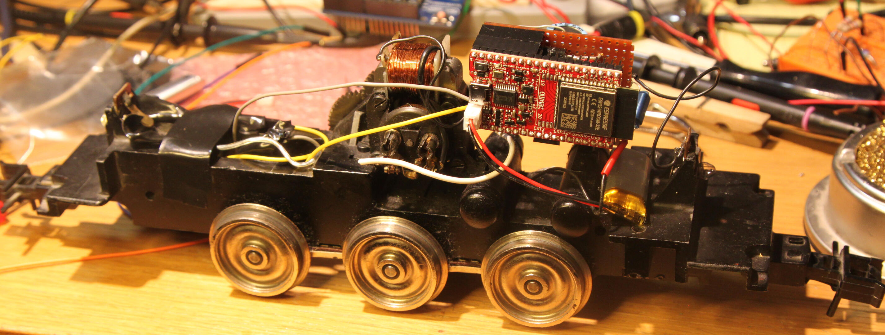
When then I found an "ESP32 DevKit LiPo" with integrated charger from OLIMEX (google for it) for less than an ESP8266 plus LiPo charger board, the decision to scrap the ESP8266 route was easy. The ESP32 is more powerful and easier to program than the ESP8266 albeit a tad bigger.
Port DCC-EX to that µCPU
The DCC-EX project uses the Arduino as it's main platform. For the optional WiFi capabilities, an ESP8266 with AT-firmware is used "on the side" as communication CPU. With the power of ESP8266 or ESP32, it should be possible to run all of the tasks of DCC-EX on that CPU. With the ESP8266 and ESP32 packages available in the Arduino IDE porting was easier than to rewrite everything against the API from Expressif. So porting DCC-EX to ESP8266 and ESP32 was started. As the ESP8266 is too limited in I/O and other HW constraints, that will be dropped and only the ESP32 route is worth following. (If you beg to differ, you can contribute to the DCC-EX project with an ESP8266 port). Currently there is a ESP32 prototype for a DCC-EX command station that can drive a DCC decoder with some limitations, for example no prog track support yet. But as there is no decoder in the engine, DCC support is not needed for this project and these limitations do not matter at all. Actually some more code could be removed.
Adopt DCC-EX to directly drive engine
The general idea was to skip the DCC step and drive the motor more or less directly with pulse-width modulation (PWM) from the I/O pins of the µCPU. So I derived DC(C)-EX Locodrive from DCC-EX. In the code, the speed and function commands are intercepted for one predefined engine and then instead the new DC-Loco module of the code controls the PWM hardware of the ESP32. Currently it could actually drive a DCC decoder in the engine as well, but as that is not necessary the DCC generation will be made optional in the future. Hence the name DC(C)-EX.
Build hardware to interface with motor and other functions
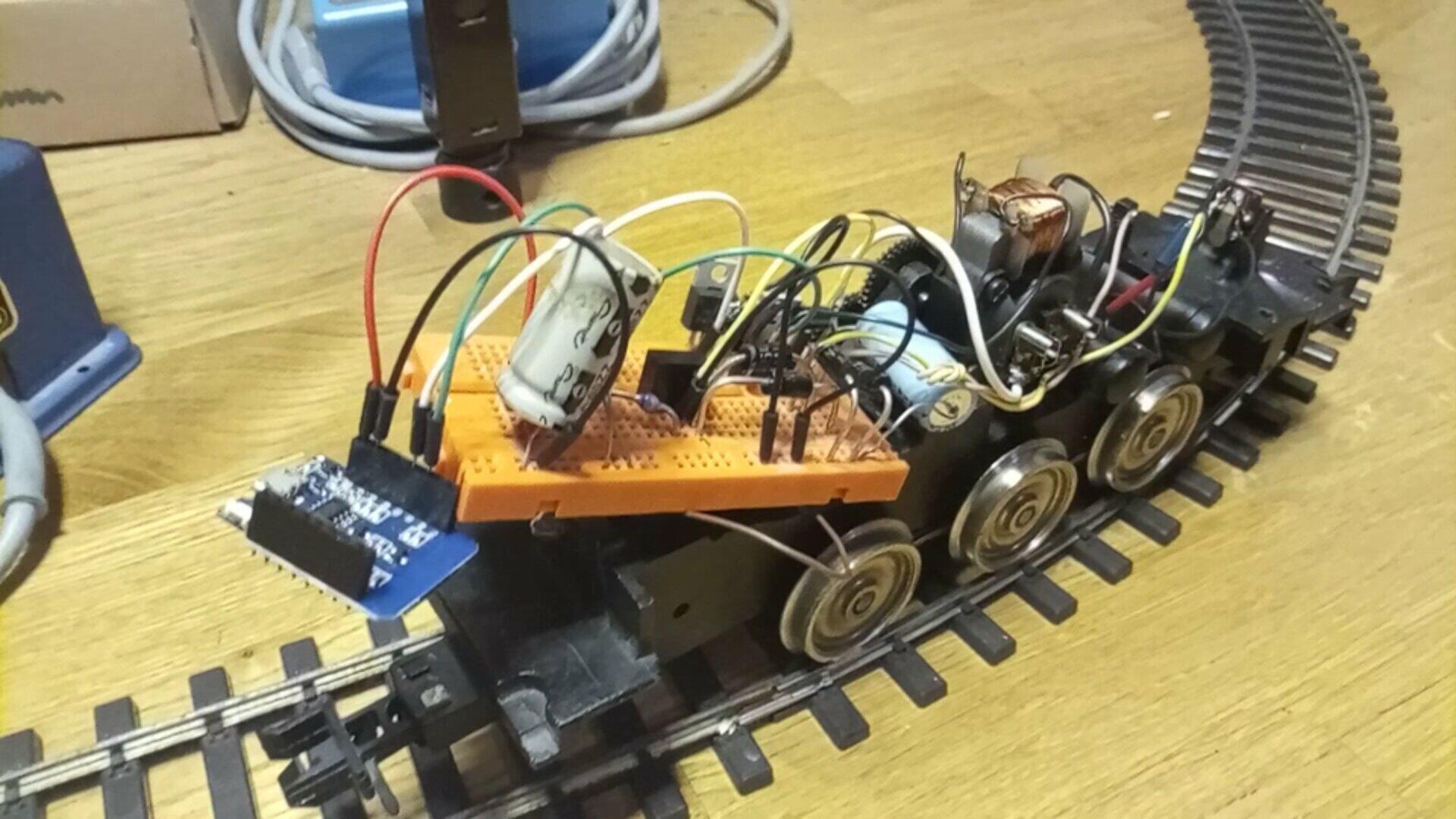
These are the schematics from the ESP8266 prototype:
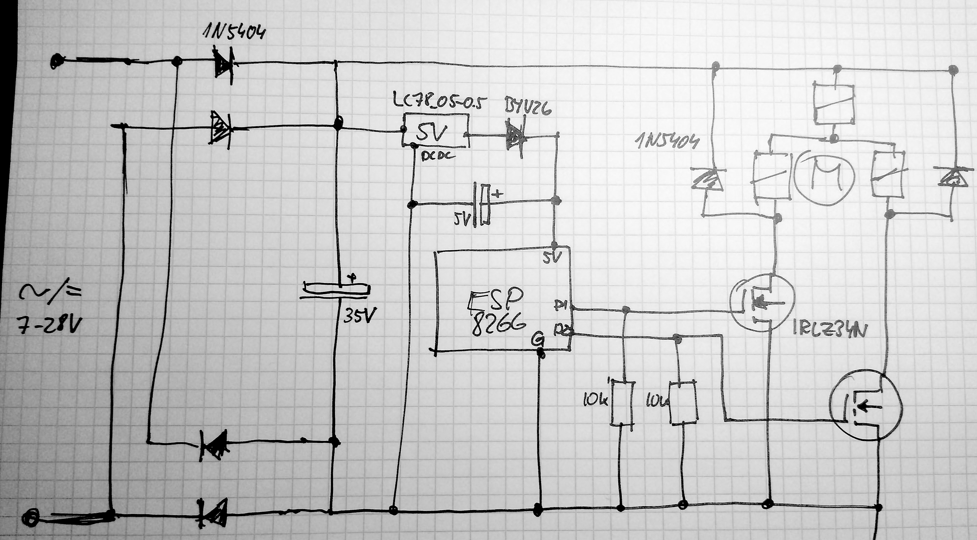
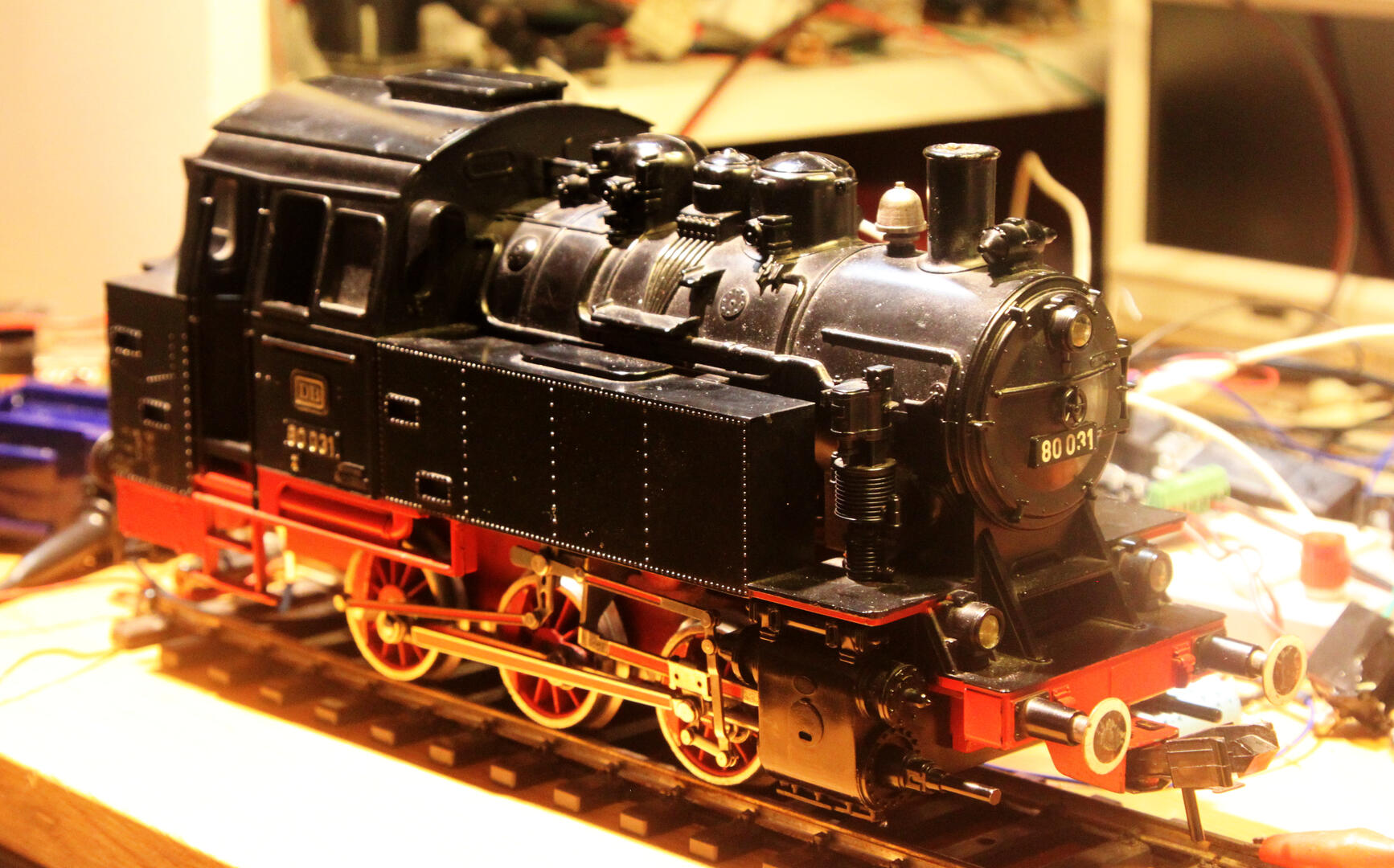
As then output pins only can supply around 20-40mA at 3.3V, you can only drive LEDs directly. For any other devices amplification is needed. For this MOSFETs are used which are cheap and durable. Most model train engines use DC motors and to run a DC motor in two directions a H-bridge would be needed. But in this special case the target was an old Märklin AC engine which uses a special kind of AC motor with double stator windings, one for each direction. Traditionally one of the windings is selected with a 24V stepper relays and thus the engine changes direction at each 24V pulse. Here a MOSFET is used for each motor winding which of course then are operated with PWM only one at the time. Even if this is a so called AC motor, these kind of motors are actually "any current" motors and will work with pulsed DC as well. Because of the inductance of the motor, the surpressor diodes are needed, otherwise the lifetime of the MOSFETs will be very short. If MOSFETs amplify for resistive loads like lights or smoke generators, this is not necessary.
The ESP8266 and ESP32 schematics are almost identical, but the BYV26 and 5V cap are replaced by the LiPo on the devkit board.
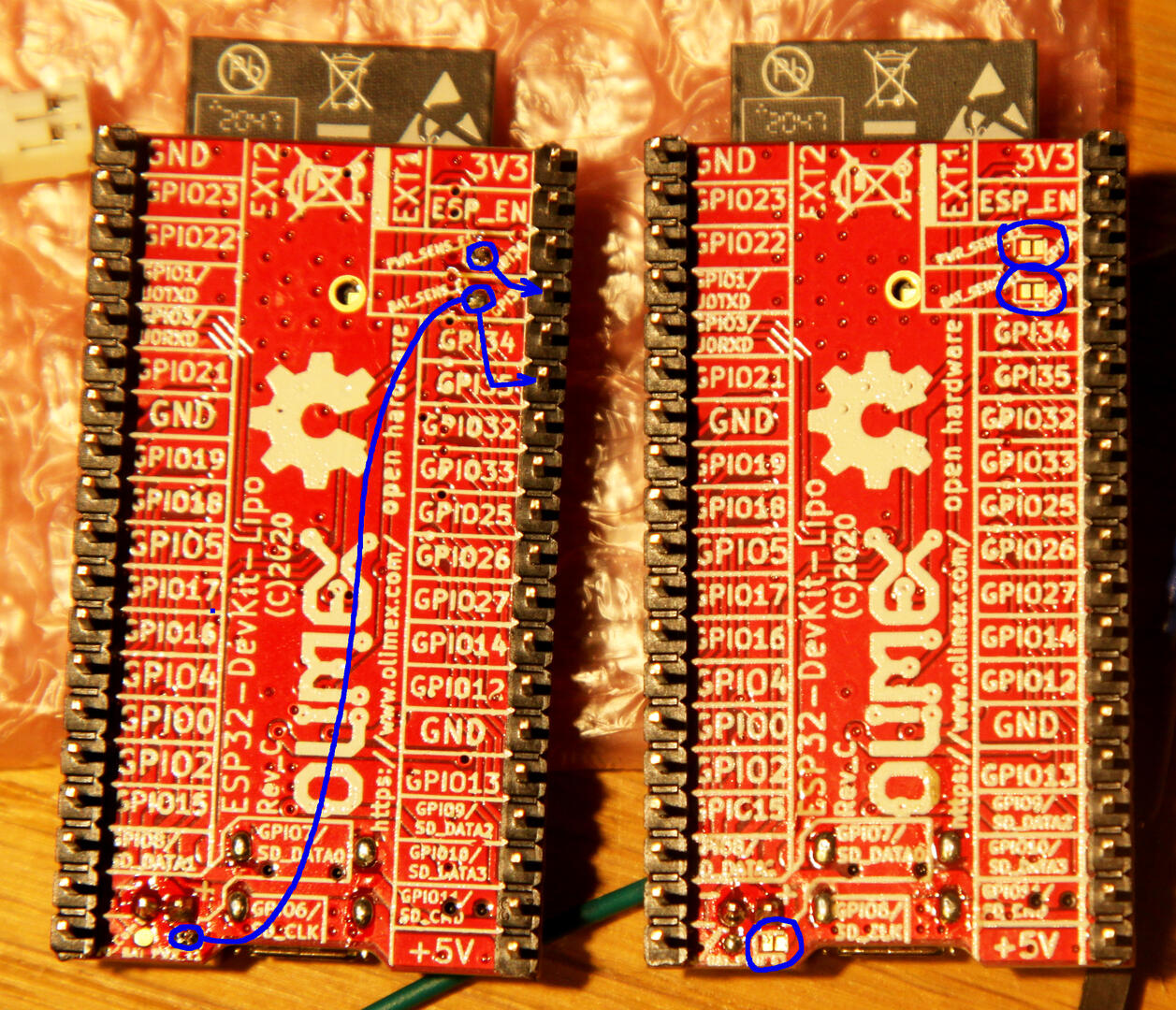
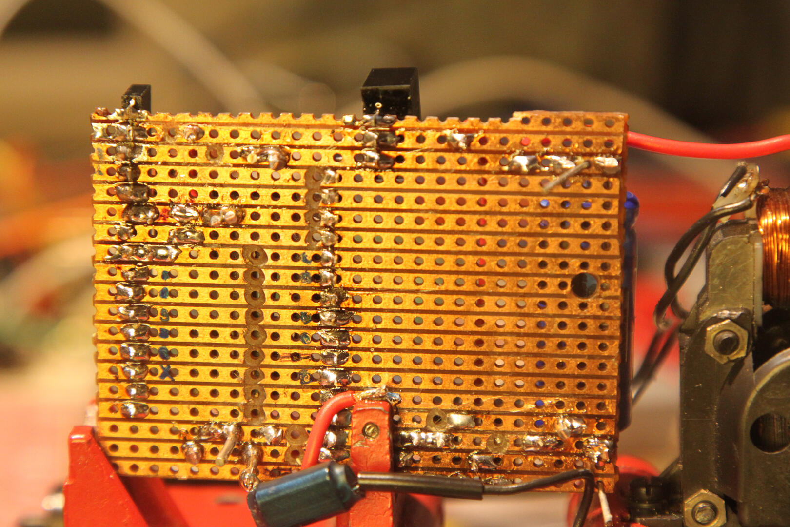
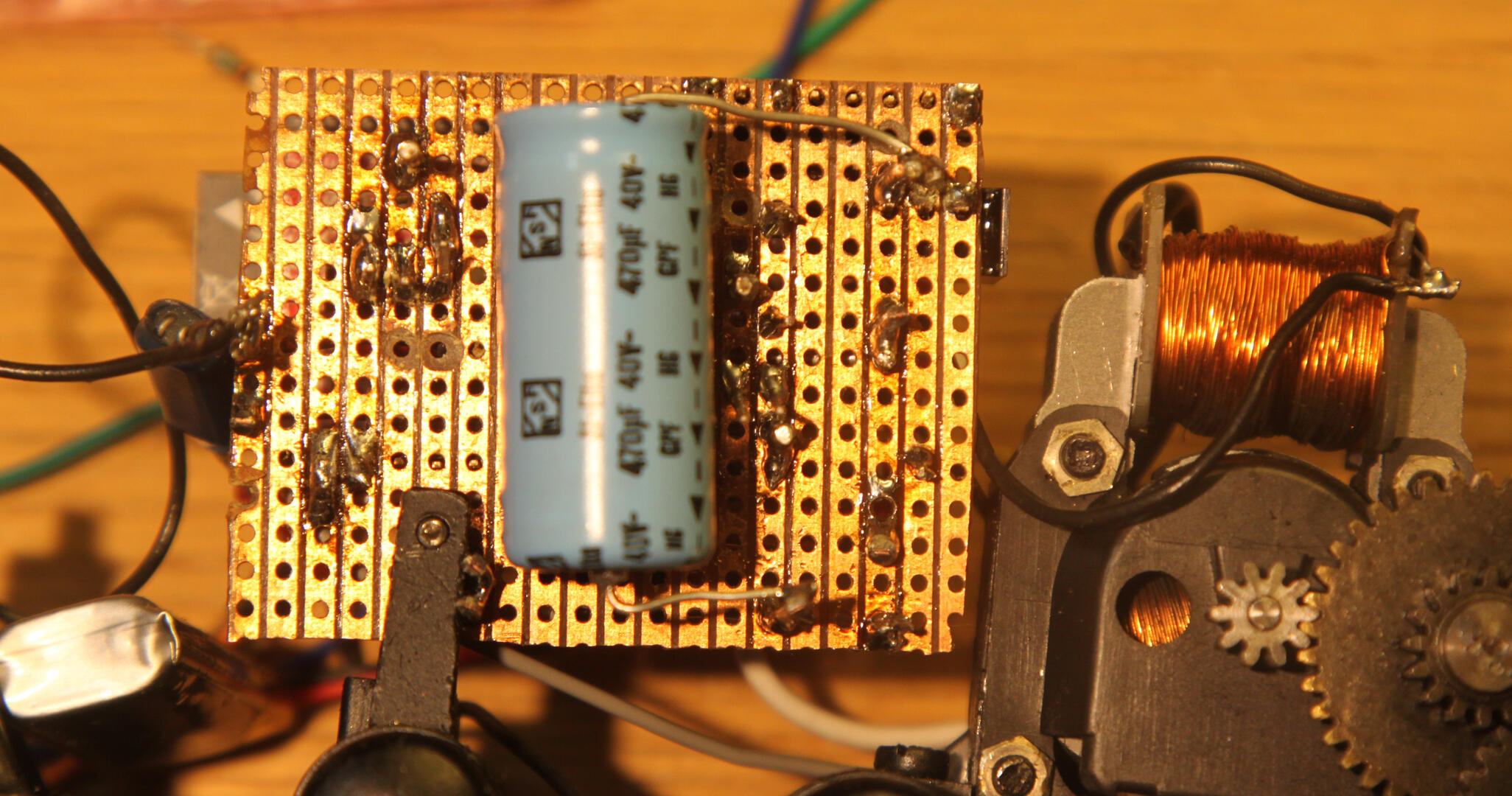
This shows which solder bridges need to be closed and which solder islands belong to which pin. The battery monitor pin is GPIO pin 35 and not pin 34 as the OLIMEX descriptions says. The placement of the solder islands is not near it's pin either, so everything is quite confusing. The voltage divider in front of the sense pins are for power 220kOhms to Vcc and 470kOhms to GND. The battery sense has a symetric voltage divider 2x 470kOhms. After closing the solder bridges this can be checked with a multimeter.
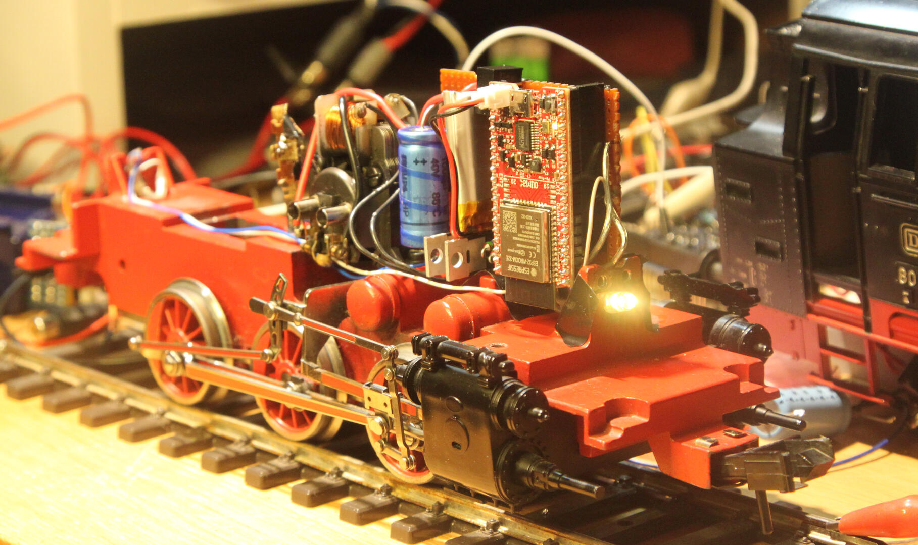
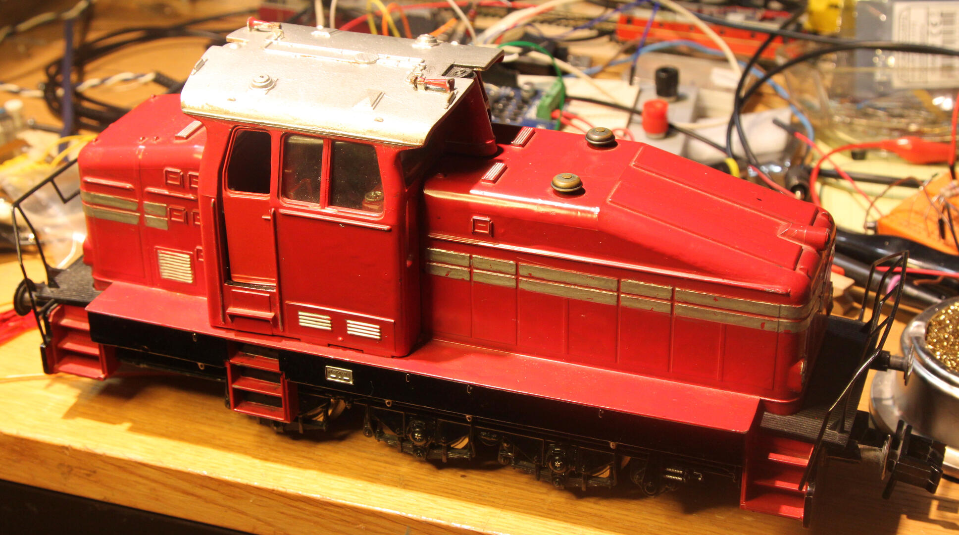
This is how the sandwich was placed on the chassis, fixated with the original screw of the direction switch. With the DHG500C that is as well the contact to the chassis. The BR80 was changed later as the outputs of the ESP must go past that place to the MOSFETs.
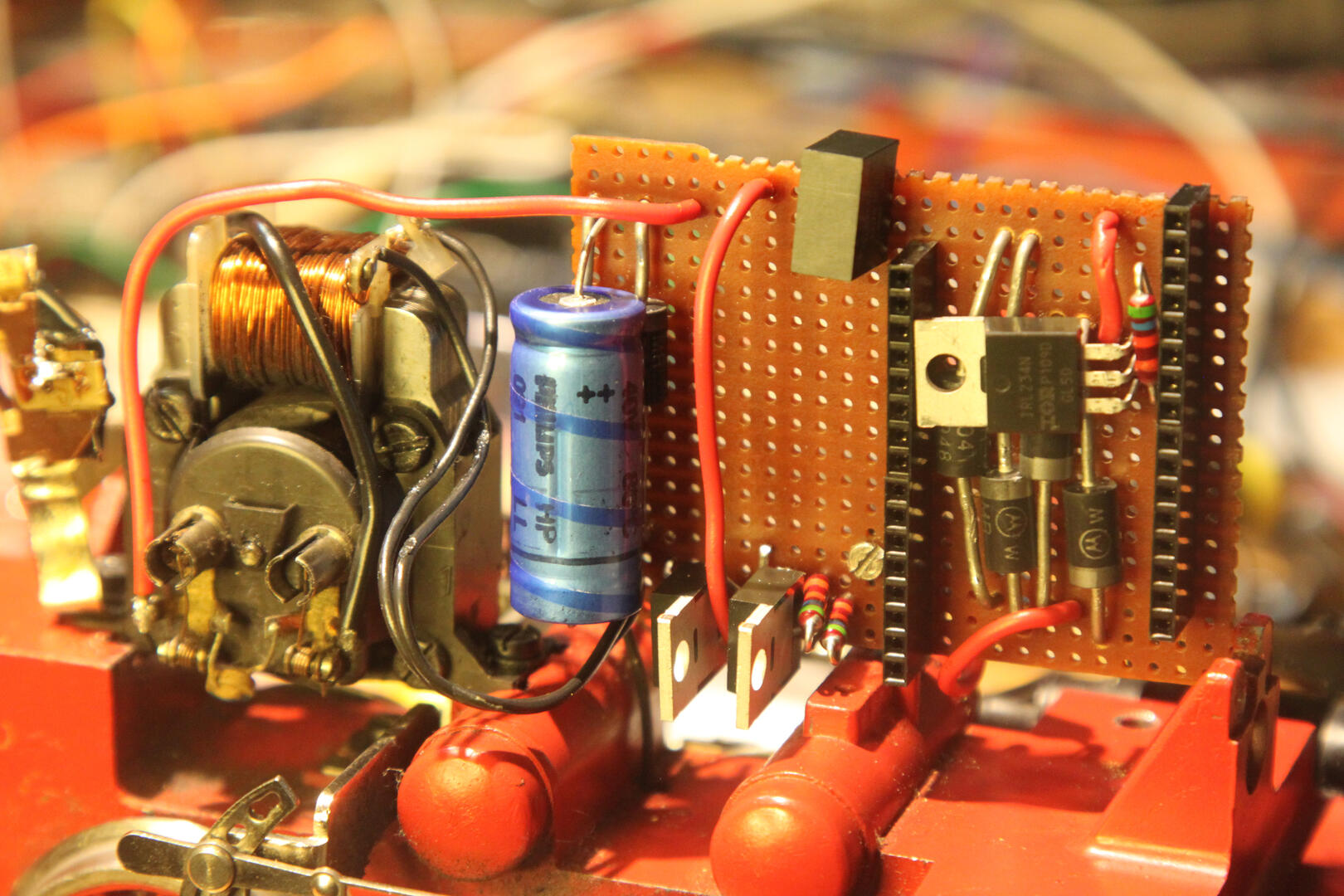
The PCB from the front (the BR80 has 3 MOSFETs because it might learn how to smoke)...
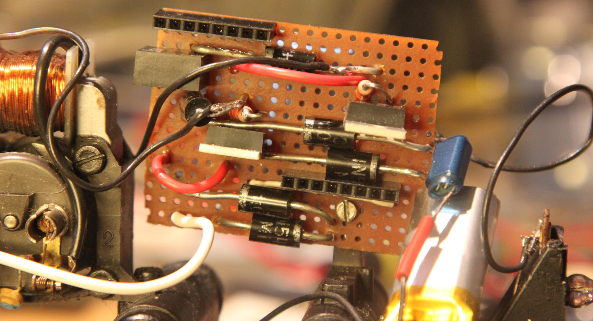
...and from the back - the BR80 not quite completed:
Everything ready:
Demo film:
Arduino IDE programming
To get the software into the ESP32, Arduino IDE and the ESP32 package for the Arduino IDE was used. This tries to make ESP32 programming more Arduino-like and succeeds with that partly. Things needed:
- Arduino IDE of at least version 1.8.13
- ESP32 boards backage for the Arduino IDE of at least version 2.0.1
- Select board: ESP32 Dev Module (not OLIMEX LiPo board)
- If you have communication/upload problems, lower upload speed to 115200
- Current branch of current code
- Configure the WiFi and IP address as described in the DCC-EX documentation
Communication with DC(C)-EX Locodriver
As every engine looks like a DCC-EX command station to the controlling application, it can be interfaced to it as easy as a DCC-EX command station, either with the DCC++ or the Withrottle protocol. As it is mobile, the USB protocol is less practical. Example how to communicate from EngineDriver (or any other WiThrottle device).
- After starting the ESP32 you have to find out the IP address, for example from your router
- Connect to IP and port 2560
- Choose engine number 2 (compiled in default)
- Have fun
- When done, lift off engine from power and choose F15. This will put the ESP32 to deep sleep thus not depleting the LiPo battery. If you forget that, the ESP32 will shutdown itself at approx 3.1V battery voltage level to protect the LiPo
- CPU will reboot/restart when engine gets power again